- 您现在的位置:买卖IC网 > Sheet目录3827 > PIC16F877A-I/P (Microchip Technology)IC MCU FLASH 8KX14 EE 40DIP
PIC16F87XA
DS39582B-page 130
2003 Microchip Technology Inc.
11.1
A/D Acquisition Requirements
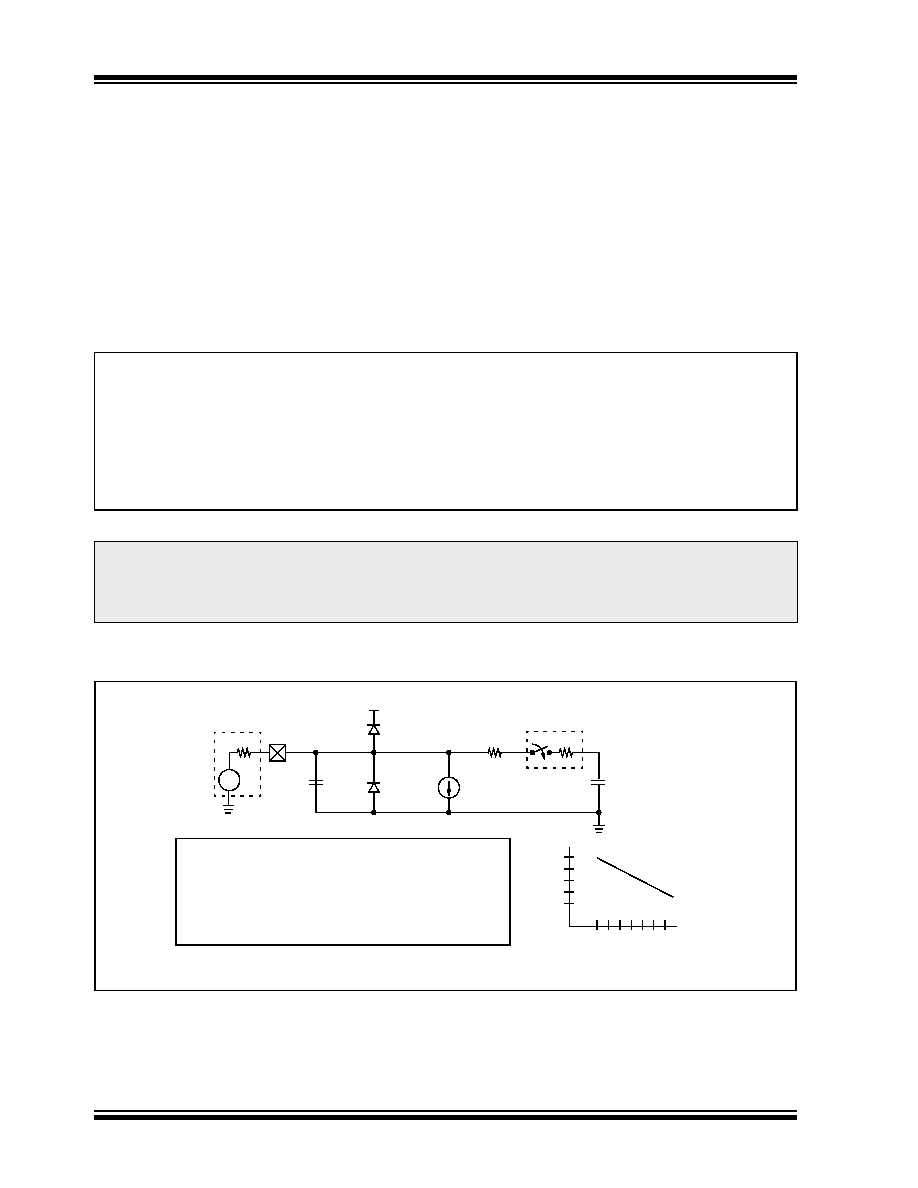
For the A/D converter to meet its specified accuracy,
the charge holding capacitor (CHOLD) must be allowed
to fully charge to the input channel voltage level. The
analog input model is shown in Figure 11-2. The source
impedance (RS) and the internal sampling switch
impedance (RSS) directly affect the time required to
charge the capacitor CHOLD. The sampling switch
(RSS) impedance varies over the device voltage (VDD);
see
The
maximum
recommended
impedance for analog sources is 2.5 k
. As the
impedance is decreased, the acquisition time may be
decreased. After the analog input channel is selected
(changed), this acquisition must be done before the
conversion can be started.
To
calculate
the
minimum
acquisition
time,
Equation 11-1 may be used. This equation assumes
that 1/2 LSb error is used (1024 steps for the A/D). The
1/2 LSb error is the maximum error allowed for the A/D
to meet its specified resolution.
To calculate the minimum acquisition time, TACQ, see
the PICmicro Mid-Range MCU Family Reference
Manual (DS33023).
EQUATION 11-1:
ACQUISITION TIME
FIGURE 11-2:
ANALOG INPUT MODEL
TACQ
TC
TACQ
=
Amplifier Settling Time + Hold Capacitor Charging Time + Temperature Coefficient
TAMP + TC + TCOFF
2
s + TC + [(Temperature – 25°C)(0.05 s/°C)]
CHOLD (RIC + RSS + RS) In(1/2047)
- 120 pF (1 k
+ 7 k + 10 k) In(0.0004885)
16.47
s
2
s + 16.47 s + [(50°C – 25°C)(0.05 s/°C)
19.72
s
Note 1: The reference voltage (VREF) has no effect on the equation since it cancels itself out.
2: The charge holding capacitor (CHOLD) is not discharged after each conversion.
3: The maximum recommended impedance for analog sources is 2.5 k
. This is required to meet the pin
leakage specification.
CPIN
VA
RS
ANx
5 pF
VDD
VT = 0.6V
ILEAKAGE
RIC
≤ 1K
Sampling
Switch
SS RSS
CHOLD
= DAC Capacitance
VSS
6V
Sampling Switch
5V
4V
3V
2V
567 8 9 10 11
(k
)
VDD
= 120 pF
± 500 nA
Legend: CPIN
VT
ILEAKAGE
RIC
SS
CHOLD
= input capacitance
= threshold voltage
= leakage current at the pin due to
= interconnect resistance
= sampling switch
= sample/hold capacitance (from DAC)
various junctions
发布紧急采购,3分钟左右您将得到回复。
相关PDF资料
MP2-HS240-51
CONN SHROUD 2-FB 240POS 5ROW
DSPIC33FJ64MC506-I/PT
IC DSPIC MCU/DSP 64K 64TQFP
DSPIC33FJ128MC802-I/SO
IC DSPIC MCU/DSP 128K 28SOIC
PIC18LF4331-I/P
IC PIC MCU FLASH 4KX16 40DIP
DSPIC33FJ128GP306-I/PT
IC DSPIC MCU/DSP 128K 64TQFP
PIC24HJ128GP306-I/PT
IC PIC MCU FLASH 128KB 64TQFP
PIC16F873-20/SO
IC MCU FLASH 4KX14 EE 28SOIC
PIC18F4431-I/P
IC PIC MCU FLASH 8KX16 40DIP
相关代理商/技术参数
PIC16F877A-I/P
制造商:Microchip Technology Inc 功能描述:IC 8BIT FLASH MCU 16F877 DIP40
PIC16F877A-I/PG
功能描述:8位微控制器 -MCU 14KB 368 RAM 33 I/O RoHS:否 制造商:Silicon Labs 核心:8051 处理器系列:C8051F39x 数据总线宽度:8 bit 最大时钟频率:50 MHz 程序存储器大小:16 KB 数据 RAM 大小:1 KB 片上 ADC:Yes 工作电源电压:1.8 V to 3.6 V 工作温度范围:- 40 C to + 105 C 封装 / 箱体:QFN-20 安装风格:SMD/SMT
PIC16F877A-I/PT
功能描述:8位微控制器 -MCU 14KB 368 RAM 33 I/O RoHS:否 制造商:Silicon Labs 核心:8051 处理器系列:C8051F39x 数据总线宽度:8 bit 最大时钟频率:50 MHz 程序存储器大小:16 KB 数据 RAM 大小:1 KB 片上 ADC:Yes 工作电源电压:1.8 V to 3.6 V 工作温度范围:- 40 C to + 105 C 封装 / 箱体:QFN-20 安装风格:SMD/SMT
PIC16F877A-I/PT
制造商:Microchip Technology Inc 功能描述:8BIT FLASH MCU SMD 16F877 TQFP44
PIC16F877A-I/PTG
功能描述:8位微控制器 -MCU 14KB 368 RAM 33 I/O RoHS:否 制造商:Silicon Labs 核心:8051 处理器系列:C8051F39x 数据总线宽度:8 bit 最大时钟频率:50 MHz 程序存储器大小:16 KB 数据 RAM 大小:1 KB 片上 ADC:Yes 工作电源电压:1.8 V to 3.6 V 工作温度范围:- 40 C to + 105 C 封装 / 箱体:QFN-20 安装风格:SMD/SMT
PIC16F877AIL
制造商:Microchip Technology Inc 功能描述:
PIC16F877AIP
制造商:Microchip Technology Inc 功能描述:
PIC16F877AIPT
制造商:Microchip Technology Inc 功能描述: